Selective Laser Melting (SLM) Process Guide
Selective Laser Melting (SLM) technology uses high-energy lasers to melt metal powder into high-density parts. To ensure manufacturing success and on-time delivery, please evaluate the following physical characteristics and design guidelines before placing your order.
[01]Equipment Capabilities & Material Mechanical Properties
Manufacturing limits, standard tolerances, and material physical property indicators
Material Properties
| Material | Density (g/cm³) | Yield Strength (MPa) | Tensile Strength (MPa) | Elongation (%) | Hardness | Thermal Conductivity | Electrical Conductivity | Electrical Resistivity |
|---|---|---|---|---|---|---|---|---|
| Stainless Steel 316L | 7.8 | 510±100520±100 | 700±100720±50 | 35±1032±10 | 93±3 HRB90±5 HRB | - | - | - |
| Aluminum AlSi10Mg | 2.7 | 240±50210±50 | 440±50320±50 | 6±38±3 | 69±3 HRB63±3 HRB | - | - | - |
| Aluminum 6061 | 2.7 | 202±40250±20 | 260±40300±20 | 14±510±5 | 90±10 HRB120±30 HRB | - | - | - |
| Precipitation-Hardening Steel 17-4PH | 7.8 | 560±1001100±100 | 900±1001300±100 | ≤21≤12.5 | 94±3 HRB41±3 HRC | - | - | - |
| Titanium Alloy TC4 (Ti6Al4V) | 4.5 | 1050±50950±50 | 1230±501015±50 | 7±313±3 | 38±2 HRC35±2 HRC | - | - | - |
| Pure Titanium TA1 | 4.51 | ≥250950±50 | ≥3501015±50 | ≥3013±3 | 38±2 HRC35±2 HRC | - | - | - |
| Tool Steel 1.2709/18Ni300/MS1 | 8 | 1050±100≥1862 | 1200±100≥1930 | 12±44±2 | 33-39 HRC48-56 HRC | - | - | - |
| Superalloy Inconel 718/GH4169 | 8.24 | 770±801150±100 | 1080±801400±100 | 25±318±5 | 30±3 HRC45±3 HRC | - | - | - |
| Copper Cu | 8.92 | 165- | 240- | 30- | 115 HV- | 365 W/(m·K) | 96% IACS | 1.8 μΩ·cm |
| Copper Alloy CuCrZr | 8.92 | ≥330- | ≥250- | ≥20- | -- | - | - | - |
Printing Dimensional Tolerance Standards
[02]Printing Risks & Mitigation Strategies (with Visuals)
Common physical issues and CAD mitigation solutions
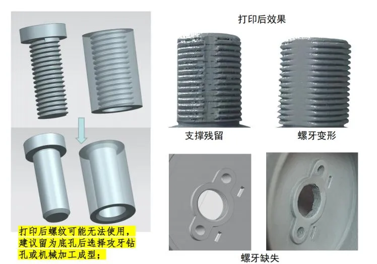
Thread Structure Printing (Internal & External Threads)
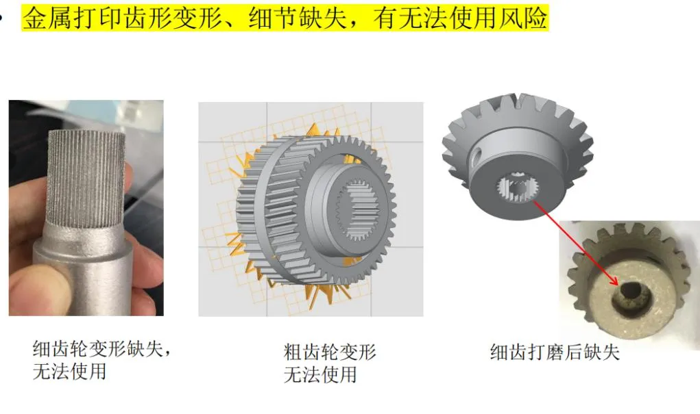
Gear / Tooth Structures
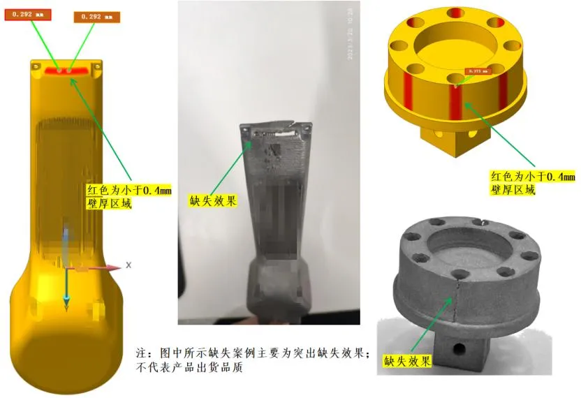
Thin Wall Limits (Wall Thickness ≤ 0.5mm)
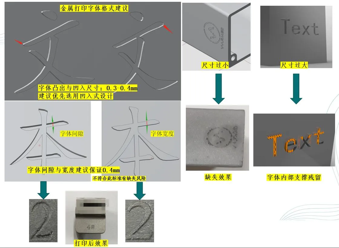
Text & Small Details (Feature Size ≤ 0.3mm)
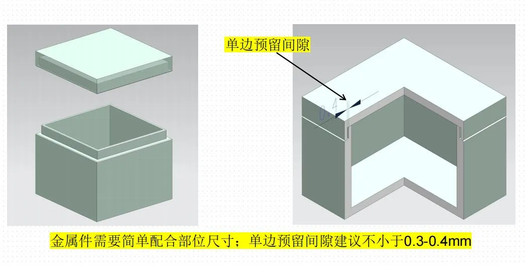
Assembly Fit Clearance
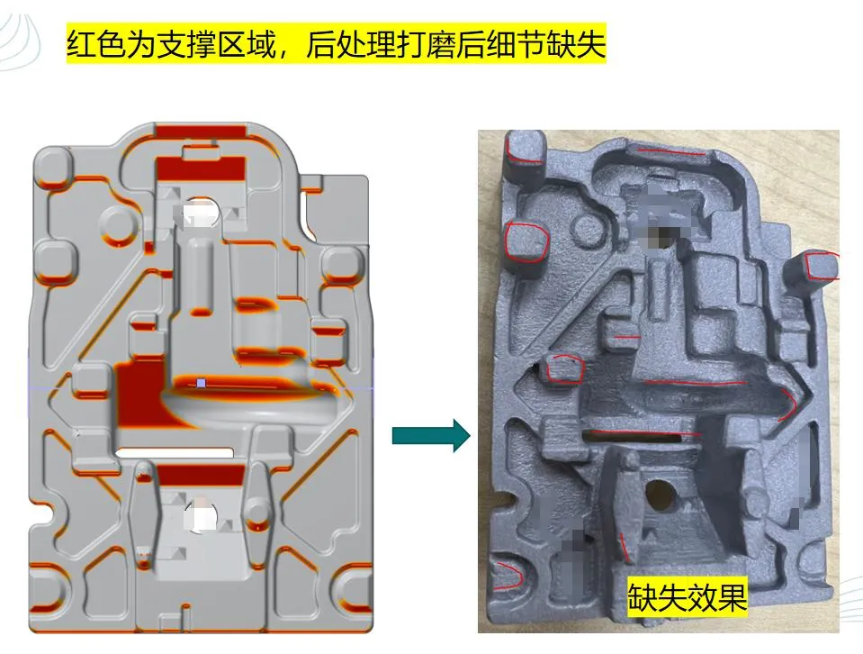
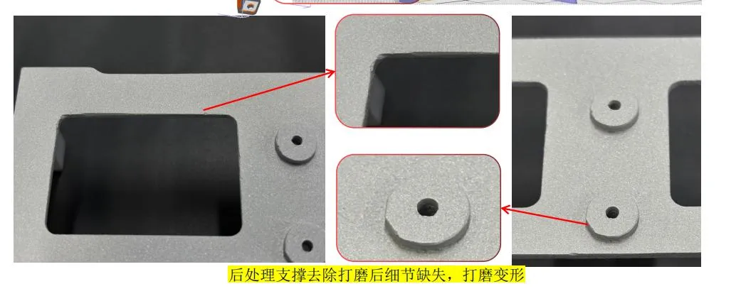
Support Surfaces & Bottom Surface Roughness
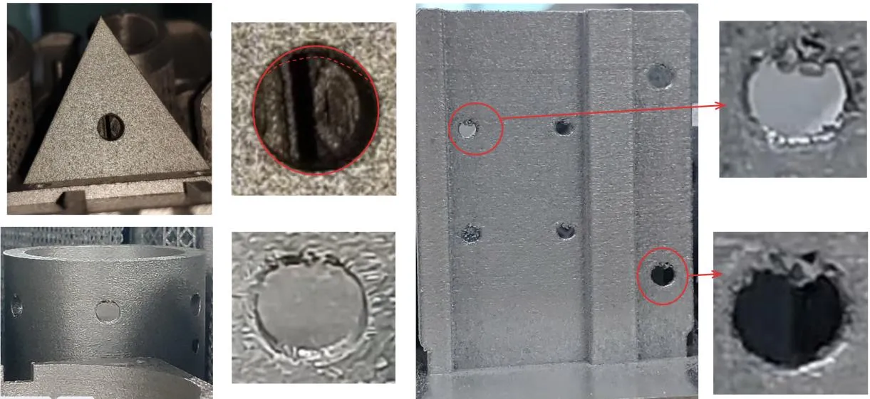
Hole Deformation & Wall Slagging
Powder Residue in Enclosed Cavities
Support Residue in Deep Slots / Internal Channels
Micro-Edge Texture Notes
[03]Design for Additive Manufacturing (DfAM) Guidelines
CAD design standards that align with slicing and melt pool support characteristics
Specification 01. Overhang & Self-Supporting Angles
Angle ≥ 45°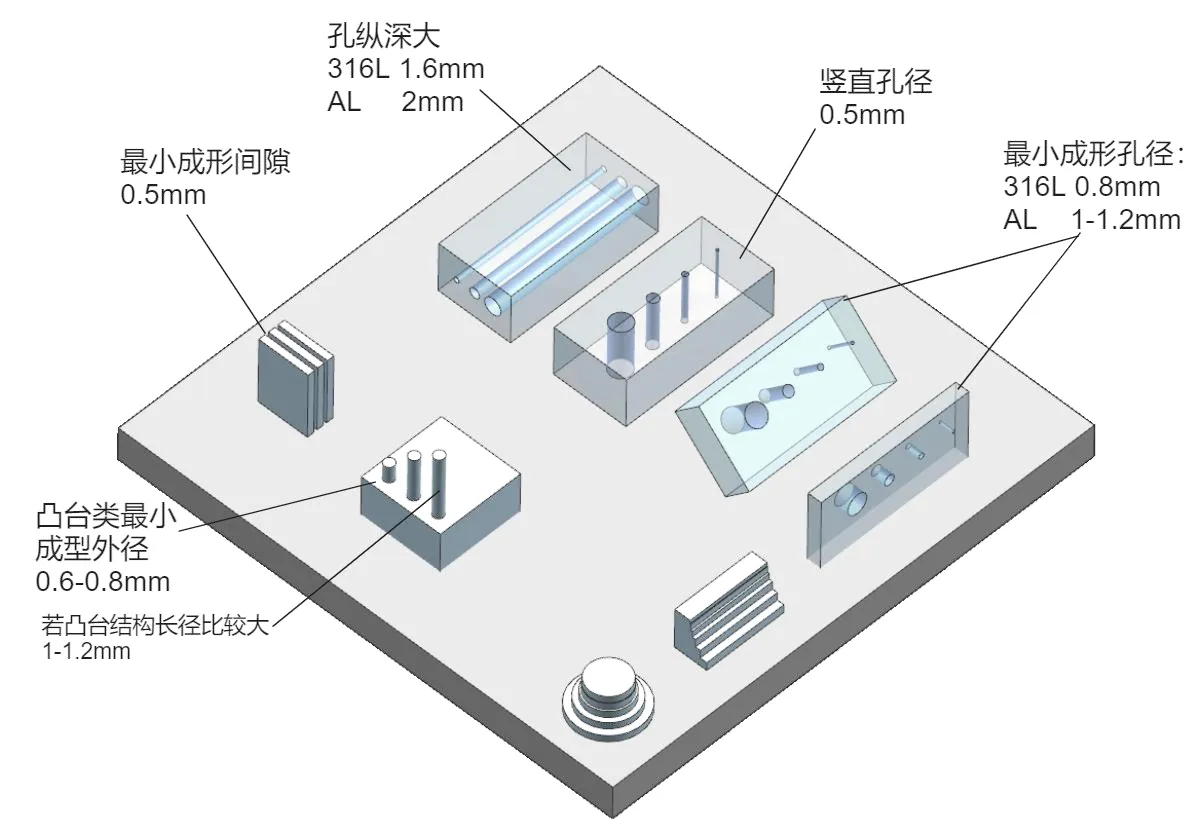
Specification 02. Channels & Powder-Escape Enclosed Cavities
Hole Diameter ≥ 2.0mm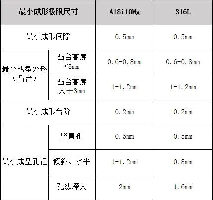
SLA Photopolymer (High Precision) Process Guide
SLA technology uses an ultraviolet laser to cure liquid photopolymer resin layer by layer, achieving extremely high surface finish and precision, making it ideal for cosmetic prototypes, validation models, and fine-featured parts.
[01]Equipment Capabilities & Material Mechanical Properties
Manufacturing limits, standard tolerances, and material physical property indicators
Material Properties
| Material | Density (g/cm³) | Heat Deflection Temperature (°C) | Yield Strength (MPa) | Tensile Strength (MPa) | Flexural Strength (MPa) | Elastic Modulus (MPa) | Elongation (%) | Hardness (Shore D) |
|---|---|---|---|---|---|---|---|---|
| White General-Purpose ABS-like Resin (8000) | 1.15 | 46 | 42 - 48 | 35 | 67 | 2370 - 2650 | 6 - 9 | 79 Shore D |
| High-Toughness Impact-Resistant Resin (Somos) | 1.18 | - | 45 - 52 | 38 - 42 | - | - | 18 - 25 | 82 - 86 Shore D |
| Fully Transparent Resin (9400) | 1.12 | - | 38 - 45 | 32 - 36 | - | - | 8 - 12 | 78 - 82 Shore D |
| High-Temperature Resin | 1.21 | 70 | 55 - 65 | 48 - 55 | - | - | 3 - 6 | 85 - 88 Shore D |
Printing Dimensional Tolerance Standards
[02]Printing Risks & Mitigation Strategies (with Visuals)
Common physical issues and CAD mitigation solutions
Warping Risk on Large Thin Sheets
Liquid Trapped in Blind Holes / Pockets
[03]Design for Additive Manufacturing (DfAM) Guidelines
CAD design standards that align with slicing and melt pool support characteristics
Specification 01. Overhang Structures & Support Placement
Angle ≥ 30°SLS Nylon Selective Laser Sintering Process Guide
SLS technology uses a CO₂ laser to sinter nylon powder into finished parts. It requires no physical support structures, offers excellent mechanical toughness and durability, and is the preferred choice for small-batch functional parts.
[01]Equipment Capabilities & Material Mechanical Properties
Manufacturing limits, standard tolerances, and material physical property indicators
Material Properties
| Material | Density (g/cm³) | Heat Deflection Temperature (°C) | Yield Strength (MPa) | Tensile Strength (MPa) | Flexural Strength (MPa) | Tensile Modulus (MPa) | Flexural Modulus (MPa) | Elongation (%) | Hardness | Notched Izod Impact (kJ/m²) |
|---|---|---|---|---|---|---|---|---|---|---|
| PA12 Nylon | 0.95 | 126 | 48 - 54 | 32 | 71 | - | 2241 | 5 - 8 | 75 Shore D | 29 |
| Glass-Fiber Reinforced Nylon (PA12 GF30) | 1.26 | 160 | 65 - 75 | 44 | 68 | 3500 - 7800 | 2415 | 5 | 82 Shore D | 4.13 |
| TPU Flexible Elastomer | 1.15 | - | 15 - 25 | N/A | - | - | - | 250 - 350 | 85 - 90 Shore A | - |
Printing Dimensional Tolerance Standards
[02]Printing Risks & Mitigation Strategies (with Visuals)
Common physical issues and CAD mitigation solutions
Powder Removal in Unsupported Cavities
Warping on Large Flat Surfaces
[03]Design for Additive Manufacturing (DfAM) Guidelines
CAD design standards that align with slicing and melt pool support characteristics
Specification 01. Self-Supporting Geometry & Clearance Design
Clearance ≥ 0.5mm